
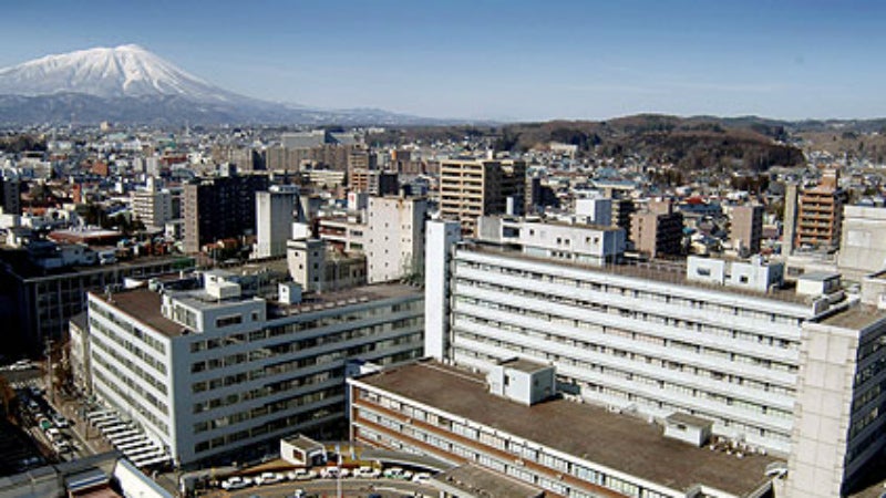
Iwate Medical University Hospital is located in Morioka City in the centre of Iwate Prefecture, at the northern end of the Kitakami Basin. It is a large hospital with 39 medical departments offering 1,050 clinical beds and handles an average of 1,600 outpatients per day.
The Iwate Private Medical School was established in 1901. This became the Iwate Medical School in 1928, and finally Iwate Medical University in 1951. The hospital contributes to regional medical services based on its philosophy of ‘Sound Spirit, Sound Medicine’.
Recommended Buyers Guides
Since 1956 it has added the Dental Hospital, Advanced Critical Care and Emergency Centre, Hanamaki Onsen Hospital, and Memorial Heart Centre. The School of Pharmacy was added in April 2007. It is the only private medical university in the Tohoku region (Fig. 1).
In April 2007, we introduced a Shimadzu SONIALVISION safire II system with a direct-conversion flat-panel detector (FPD) that can conduct tomosynthesis. Tomosynthesis is mainly used for orthopedic surgery at this hospital. This paper reports on basic investigations into metal artifacts in tomosynthesis of the scaphoid bone with Herbert screw fixation. It also introduces the effectiveness of the tomosynthesis image enhancement software that was introduced on a trial basis in October 2008 on tomosynthesis images deemed to have clinical utility at this hospital.
Basic investigation into metal artifacts in tomosynthesis
Scaphoid bones with Herbert screw fixation are traditionally evaluated using simple X-ray images and stress radiography, as artifacts make computed tomography (CT) inappropriate for these follow-up observations. As tomosynthesis is reported to be less affected by artifacts than CT¹, we evaluated the possibility of using it for follow-up observations of the scaphoid bone.
Tomosynthesis artifacts vary due to the radiography parameters and image processing parameters. Positioning may also affect the area of interest. We conducted simulations of tomosynthesis on the scaphoid bone after screw fixation to determine the effects on artifacts of changing the radiography parameters and image processing parameters and the effects of the positional relationship of the metal in the X-ray tube scanning direction.
Method
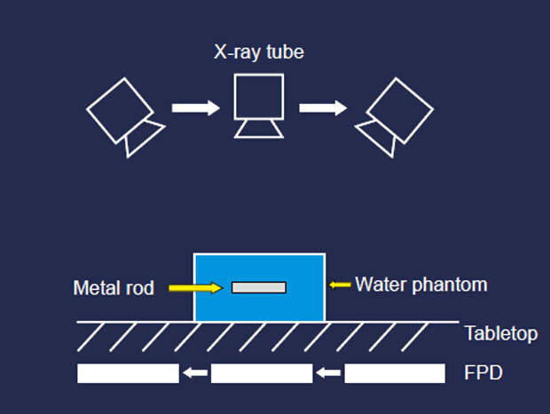
A water phantom containing a 3mm-diameter metal rod representing a screw was positioned on the tabletop with the rod long axis parallel to the tabletop (Fig. 2). Tomosynthesis was conducted with radiography conditions 50kV and 4mAs/pulse, 5s tomography time, and fixed 9in effective field size. FBP image reconstruction was used. The following parameters were changed:
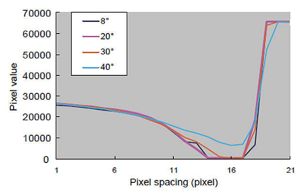
(1) Tomography angle (8°, 20°, 30°, 40°)
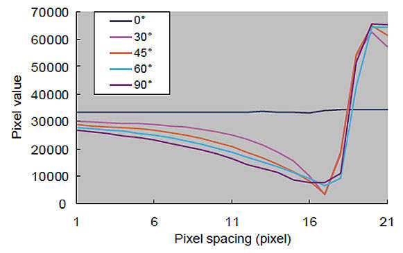
(2) Inclination of metal rod long axis with respect to the X-ray tube scanning direction (0°, 30°, 45°, 60°, 90°)
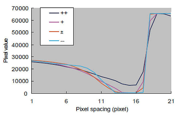
(3) Image reconstruction slice thickness (++, +, ±, -, –)
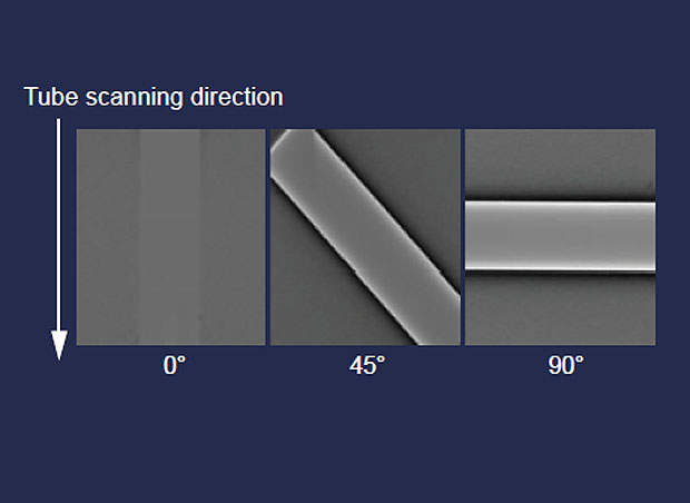
The angles of 0° (rod parallel to X-ray tube scanning direction), 45°, and 90° were used for (2) inclination of metal rod long axis with respect to the X-ray tube scanning direction (Fig. 3). Parameter (3) image reconstruction slice thickness is an image processing parameter for frequency band limitation² that is intended to reduce noise. Slice thickness (++) indicates the maximum slice thickness and (–) indicates the minimum slice thickness.
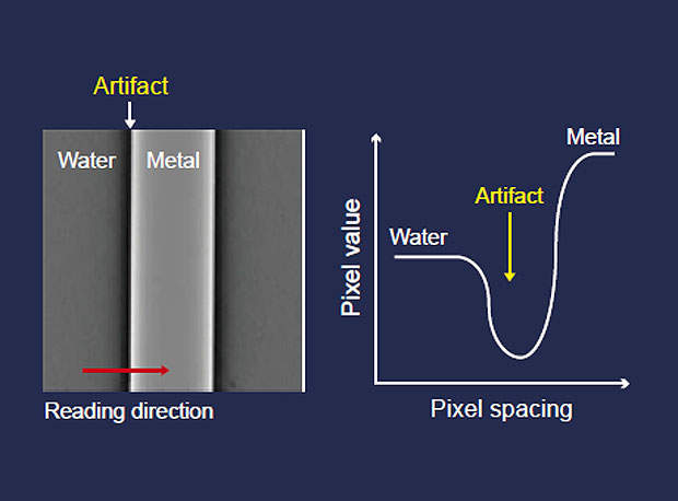
Artifacts were analyzed using Image J image analysis software on DICOM data obtained from radiography. Data was read in a direction perpendicular to the metal rod long axis. It was used to create an artifact profile curve, with the pixel value along the vertical axis and pixel spacing along the horizontal axis (Fig. 4).
Results and comments
1. Effect of tomography angle on artifacts: the results show that the minimum artifact occurs at 40° tomography angle (Fig. 5). This tomography angle produces the minimum artifact because the projected information is acquired from multiple directions at high tomography angles.
2. Effect of inclination of metal rod long axis with respect to the X-ray tube scanning direction on artifacts: the artifact effect decreases as the metal rod angle becomes closer to parallel to the X-ray tube scanning direction (Fig. 6). The inclination of the scanned X-rays increases as the metal rod angle deviates from 0°, which increases the filter effect of the FBP method on both sides of the metal rod, resulting in undershoot artifacts.
3. Effect of image reconstruction slice thickness on artifacts: little artifact occurred at the greatest slice thickness (++) (Fig. 7). This is believed to result from reduced noise due to stronger artifact reduction processing for image reconstruction with greater slice thicknesses². However, if the slice thickness is set greater than the thickness of the radiography target, partial volume effects may result in indistinctness of the area of interest. Therefore care is required when determining the image reconstruction slice thickness for clinical applications.
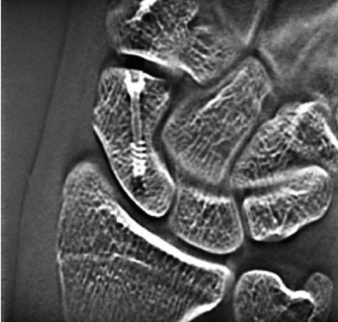
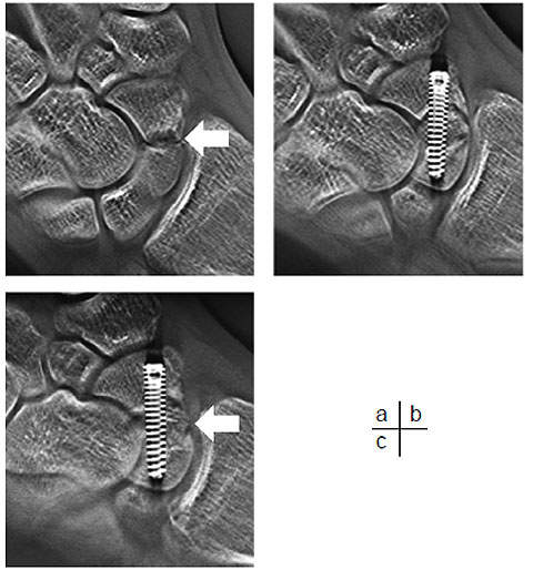
Consequently, to minimize artifacts in tomosynthesis of the scaphoid bone, this hospital positions the screw axis parallel with both the tube scanning direction and the tabletop and uses 40° tomosynthesis angle. The image reconstruction slice thickness parameter was set to the minimum thickness (–) to set a 1mm slice pitch. Fig. 8 shows an actual tomosynthesis image of the scaphoid bone. The black artifact band apparent along the length of the screw does not affect on the evaluation of bone union at the margins of the scaphoid bone. As tomosynthesis permits the evaluation of screw fixation of the scaphoid bone, we do not currently conduct stress radiography.
Clinical cases where tomosynthesis was effective
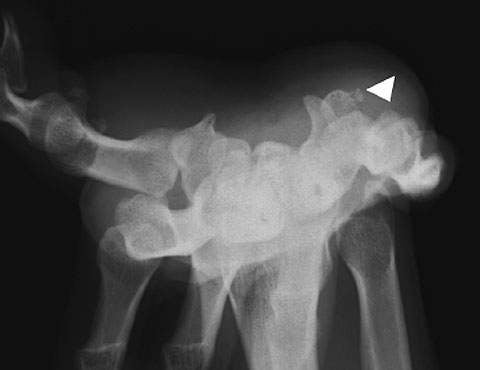
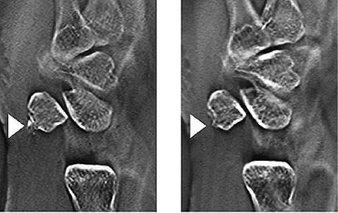
Case 1 – 29-year-old male: the patient visited the hospital complaining of unexplained pain in the right volar wrist during flexing for the past few months. Carpal tunnel radiography confirmed calcification at the ulnar side of the pisiform bone (Fig. 9), although it was not apparent in general radiographs from two directions. Lateral tomosynthesis of the wrist joint revealed a calcified deposit. Another tomosynthesis image taken two months later confirmed repair at the exfoliated area (Fig. 10).
Case 2 – 5-month-old female infant: visited the hospital due to a congenital hip dislocation. The patient was cast-immobilized after a closed reduction of the hip dislocation. Tomosynthesis was performed, as observations were not possible by frontal general radiography of the hip joints due to interference by the cast. The tomosynthesis image clearly shows the femoral heads. It shows no displacement in the hip joints (Fig. 11).
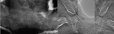
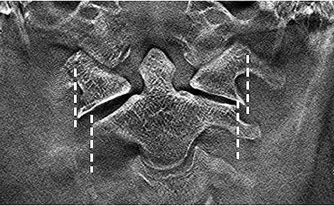
Case 3 – 58-year-old female: a patient who had fallen down stairs at home was immediately hospitalized after CT confirmed a Jefferson fracture. The treatment for a Jefferson fracture is determined according to whether the transverse ligament is intact or broken. This is evaluated from the degree of lateral dislocation of the lateral mass of the atlas with respect to the lateral mass of the axis on both sides³. Frontal tomosynthesis of the cervical vertebrae was performed the day after hospitalization. It provided better evaluation of the lateral mass of the atlas and axis than general radiographs or CT (Fig. 12). Conservative treatment by Halo vest fixation was performed.
Case 4 – 15-year-old male: injured right hand in a fall from a bicycle and visited our hospital one month later, after diagnosis of fracture of the scaphoid bone at another hospital. Tomosynthesis performed on arrival at the hospital confirmed a bone defect in the scaphoid waist. A bone graft with screw fixation and cast immobilization was performed two months after the injury. The fracture line in the scaphoid bone has become indistinct in the tomosynthesis image taken in the 16th week. This is assumed to result from progress of bone union (Fig. 13).
Tomosynthesis image enhancement software
In conventional tomosynthesis images, the graininess deteriorates at the specified sectional plane (centre sectional plane, and approximately 20mm above) in comparison with the other sectional planes. The phenomenon becomes more pronounced as the image reconstruction slice thickness becomes thinner. Shimadzu has installed trial image enhancement software to overcome this problem. The results are described below.
Improvement of graininess at the centre sectional plane
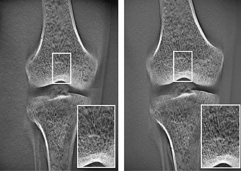
Due to the principle of operation of tomosynthesis, the minute sensitivity discrepancies between sensors are magnified at the centre sectional plane (the virtual centre of the linear trajectory) during image reconstruction calculations and this tends to cause deterioration in graininess. The new image enhancement software offers ‘air calibration’.
Air calibration periodically conducts one normal tomosynthesis operation for each field size to acquire the optimal calibration data for each tomosynthesis scan trajectory in order to improve the graininess. Fig. 14 shows images before and after introduction of the software. The graininess of the overall image has clearly improved. This overcomes the problems at the thinnest image reconstruction slice thickness setting, and we currently use this setting without any problems.
Enhanced clarity of reconstructed images
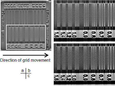
Grid movement control during tomosynthesis eliminates the need for the conventional moire elimination filter. It improves the horizontal resolution that was sacrificed when a moire elimination filter was used (Fig. 15).
Reduced X-ray exposure dose
The FPD high-gain mode achieves image quality equivalent to the conventional method using just one-half the radiography conditions. This results in reduced X-ray exposure dose.
Conclusions
At this hospital, tomosynthesis is mainly used for orthopedic surgery. We believe that the tomosynthesis images can confirm the diagnosis in many cases.
Tomosynthesis is available on demand at this hospital, unlike the reservation system used for computed tomography (CT). Tomosynthesis can create an arbitrary sectional plane from a single scan operation. The examination is completed quickly, similar to general radiography. As the tomosynthesis function is installed on a fluoroscopy instrument, positioning is very easy under fluoroscopy. This achieves good reproducibility of the three-dimensional movements that are required for the scaphoid bone.
Tomosynthesis images are useful for diagnosis, as FBP reconstructed images clearly reveal trabecular bone and the images can be further adjusted or reconstructed on a workstation to suit the diagnostic aim. The X-ray exposure dose is lower than computed tomography (CT)4 and the newly developed image enhancement software further reduces the dose. Tomosynthesis is used together with plain bone X-rays in the field of orthopedic surgery. The opportunities to use functional imaging under fluoroscopy are also increasing. However, discrepancies occur between bone X-rays. We have many years’ experience with CR images. How to create bone images of equivalent quality with the SONIALVISION safire II tomosynthesis function is an essential subject of future investigation.
Computed tomography (CT) continues to rise in popularity. However, through its application to lung cancer diagnosis and the creation of 3D imaging systems, tomosynthesis is expected to form a new modality positioned between general radiography and CT.
Acknowledgement
I wish to express my gratitude to the clinical instruction I received from Dr Katsuro Furumachi on the orthopedic surgery course at this university.
Author: Shouta Miura
References
1. Shigeru Okamoto. Digital Tomosynthesis in the Thoracic and Orthopedic Fields by Direct-Conversion FPD. INNERVISION. 2007; 22 (2): 14-16
2. Yukihiro Takumi. Development of a Digital Tomosynthesis Workstation. Shimadzu Review. 2005; Vol. 61, 127-134
3. Osamu Kataoka, Shigeo Toya ed.: Clinical Study of the Upper Cervical Vertebrae. Nankodo. 2000: 162
4. Hiroyasu Yano. The Effective Use of Tomosynthesis in Orthopedic Surgery -Follow-up after procedures using metal-. MEDICAL NOW. 2006; No. 59, 11